Hi All,
this is the logbook of my tracer implementation based on "tracer", Zorrikio design.
The original model is flying fine and looks like this way:
I have slightly changed a few details and used a mini CC3D atom. This is a cheap flight control board that is simple and small. This allows to reduce weight and free some space in the model. Normally I don't think a racer will require a GPS navigation (although the CC3D has this possibility).
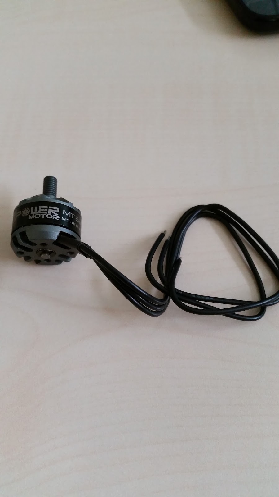
Motor specs are available here from iflight site:
http://www.iflight-rc.com/ipower-mt1806-2300kv-w-thread-shaft.html
I got the motors that are very lightweight from
http://www.iflight-rc.com/.
These motors are also small but look good and well made.
A good review of the internal structure of the motor is available here:
http://www.rcgroups.com/forums/showthread.php?t=2219404
Thanks Aki and Ted.
With these I started the assembly from the two front arms:
These were built using a 12 mm OD 10 mm ID 3K CF tube. The motor mount have been bought from Pitlab (
http://www.pitlab.com/pitlabshop/accesories-for-multirotors.html) that was close to me in Europe. The design was already created by Roberto and Aki from IFlight helped me with the cad based CF cutting. This has allowed to have very precise plates as main multi rotor frame.
The complex part to build has been the tail mechanism and the linkage between the tail and the motor that must be able to rotate driven by the servo.
I used a second CF tube 10 mm OD 8 mm ID for the tail arm. This is internal to the other tube I also used for the front arms (12 mm OD 10 mm ID 3K CF tube). Please note: only the tail arm has a tube inside a tube.
The rotating mechanism is all hidden
Movement is smooth and easy.
The tail tube containing the mechanism is closed at the end.
Some parts for the tail arm are coming from spares used in most of RC helicopters' tail. For example the servo and the two servo supports keeping the servo on the tube.
I used a third motor mount to link and drive the servo to the rotating part of the tail.
I used a CF shaft for the tail mechanism, to minimize the weight. A CF tube has also been used as a spacer between the internal tail ball bearings.
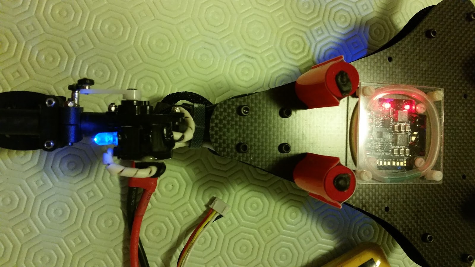
The overall assembled result is looking fine and small.
The mini CC3D nano atom is really small.
The total model weight is enough reduced I think. The look is fine too I think :)
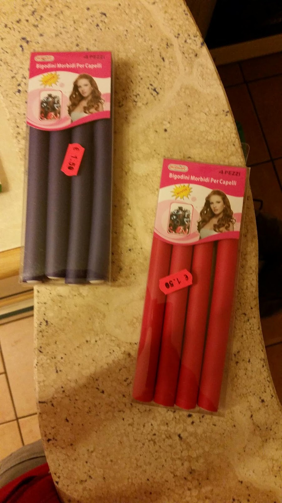
The landing gear has been made with neoprene tubes used usually by women for their hair. I have added some very visible colors so that when I land on the grass it is easier to see where the model is.
Let's say we can stay around 350 gr. No battery. No FPV parts.
I have started with the field test this blog update, to be sure I was posting something able to flight.
Aki from IFlight advises to use 5x45 plastic props. Initial tests have been done with 5x30, just to test lift off.
The time required to put all parts together, when acquired, has been about 2 or 3 days.